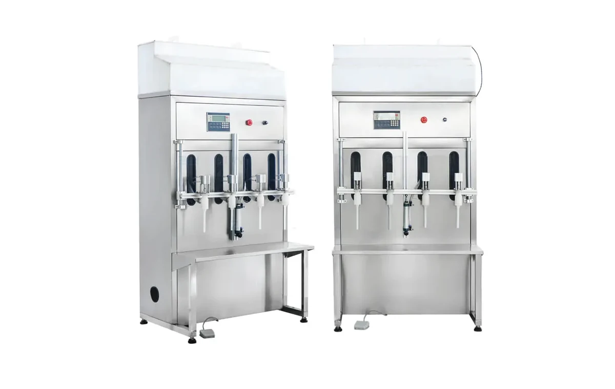
Automatic anti-corrosion filling
For bleach, acids, alkalis and aggressive liquids where non-metal product contact parts may be required.
Read moreAutomatic fillers
Automatic chemical fillers are used where conveyor-fed containers, repeatable fill cycles, multi-head dosing and integration with capping, labelling and coding are needed. The equipment should still be selected around liquid behaviour, container stability and site constraints.
Specification
Automatic filling is usually justified when manual handling is limiting output, fill consistency, operator time or repeatability. It can also improve the control of splash, foam and line presentation when the right filling principle is chosen.
Choose your equipment
Automatic does not mean one machine type. The principle changes with the product and pack.
For bleach, acids, alkalis and aggressive liquids where non-metal product contact parts may be required.
Read more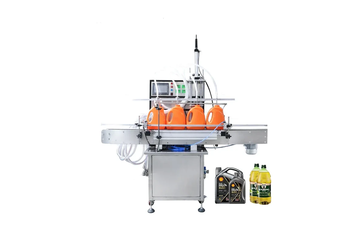
For foamy home-care and industrial cleaning liquids where fill profile, nozzle movement and capping method matter.
Read more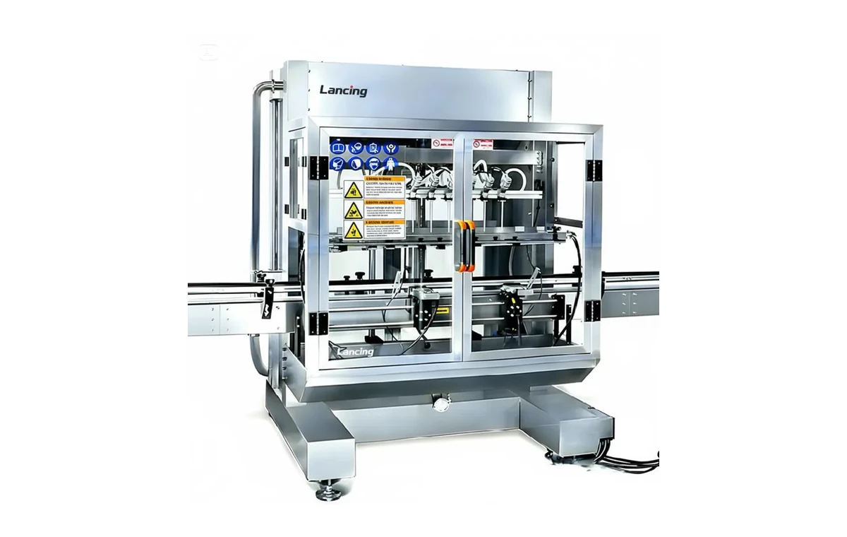
For low-viscosity specialist liquids requiring careful project review around environment and line specification.
Read more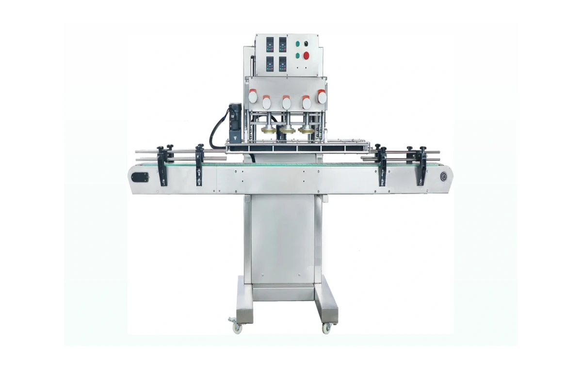
For projects where filling, closure control, labelling, conveyors and coding need to work as a line.
Read moreComparison
| Input | Needed detail | Why it affects the line |
|---|---|---|
| Liquid | Viscosity, foaming, corrosiveness, flash point, temperature | Chooses pump, nozzle, valve, wetted parts and controls |
| Container | Height, diameter, neck, material, stability | Affects guides, conveyors, nozzle pitch and starwheel or inline handling |
| Closure | Screw cap, trigger, pump, plug, induction seal | Controls capping method and line balancing |
| Output | Bottles/minute or containers/hour | Determines number of heads, conveyor length and accumulation |
| Changeovers | SKU count and frequency | Determines adjustment, tooling and operator setup time |
Process
Check how the chemical fills, foams, splashes and shuts off.
Confirm whether the bottle, jerrycan or pail is stable enough for the target speed.
Confirm closure behaviour, torque target, label placement and coding needs.
Plan utilities, access, guarding, operator positions and future expansion.
FAQ
Output depends on fill volume, product behaviour, number of heads, container handling, capping speed and changeover requirements. A project should be quoted from actual samples and targets rather than a generic speed claim.
Yes, where the filling method, nozzle design and fill profile are selected for foaming behaviour. Detergents and cleaners should be discussed as a product family rather than a generic liquid.
Yes. Automatic chemical filling projects are often strongest when the capper, labeller, conveyors and coding requirements are reviewed at the same time as the filler.
Speak to Lancing
Send the product, fill volume, container, closure and target output. Include SDS and compatibility notes where relevant.
Automatic line engineering
An automatic chemical filling machine must work with product supply, container presentation, capping, labelling, coding and discharge. The useful output is the number of acceptable finished packs produced under agreed conditions, not the fastest cycle achieved by the filler on its own. Line balance, replenishment, short stops, cleaning and changeover all belong in the commercial specification.
Automatic platforms can use peristaltic, diaphragm, piston, gear, lobe, flow or weigh-based dosing where technically suitable. The choice depends on chemistry, viscosity, foam, particulates, dose range, pressure, cleaning and the required cut-off. A multi-head machine also needs a method for checking head-to-head performance and identifying a blocked or drifting channel.
For example, Lancing’s published LUSVPP80C automatic peristaltic platform uses four hose-contact channels and an HMI-set volume, with a published recommended range of approximately 10–500 ml. That is a useful reference for compatible small-dose projects, but final tubing, flow, output and dose performance must be confirmed with the actual product.
Acceptance evidence
| Test | Why it matters | Evidence to record |
|---|---|---|
| Cold start and restart after pause | Product may settle, drain, warm or aerate while stopped | First-pack fills, drip behaviour, purge requirement and time to stable operation |
| Low and high fill formats | The metering and nozzle window may behave differently at each extreme | Measured fills, cycle time, recipe settings and required change parts |
| Upstream/downstream stop | A real line must control accumulation without spills or collisions | Interlocks, no-container/no-fill response, controlled stop and recovery sequence |
| Changeover and cleaning | Downtime and cross-contamination risk affect usable capacity | Method, tools, retained product, flush volume, access and restart checks |
| Timed production run | Short demonstration cycles do not prove sustained good output | Good packs, rejects, micro-stops, operator interventions and agreed exclusions |
Page ownership
This page keeps the focus on automatic filling where chemical behaviour changes the specification. Broader automatic filling technology belongs on Automatic Filling Machines UK. Where the project extends to full-line controls, accumulation, capping, labelling, FAT and SAT, continue with Packaging Lines UK.
Automatic filler FAQ
Head count follows the required good output, actual fill time, container pitch, conveyor behaviour and cleaning burden. More heads do not automatically improve the line if product supply, capper or labeller becomes the limiting stage.
Only after each formulation and cleaning route is reviewed. Shared wetted parts, hoses, seals, dead legs and retained product may limit a multi-product duty or require dedicated product paths and change parts.
The control philosophy should prevent dosing into an empty position, manage the associated head or lane safely, retain traceable status and recover without creating a spill or ambiguous pack.
Agree a timed run using representative product, packs and operators. Count acceptable finished packs and record rejects, stops, replenishment and interventions rather than quoting only the filler’s mechanical cycle rate.
Possibly, after their working height, controls, condition, guarding, speed, format range and documentation are surveyed. The interface and responsibility boundaries should be written into the project scope.
Automatic project brief
Share the product, containers, fill range, sustained output, existing equipment, available layout and cleaning plan.
Sustained automatic output
An automatic chemical filling machine is part of a controlled line. Its useful output depends on product supply, container presentation, fill profile, cap availability, downstream acceptance and recovery after routine stops. Define the measurement window and excluded conditions before a speed statement becomes an acceptance criterion.
| Line condition | Control question | Acceptance evidence |
|---|---|---|
| Product replenishment | How are pressure, level, suction, aeration and low-product conditions detected or controlled? | Run at representative full and low supply conditions with alarms and restart recorded |
| Container infeed | How are gaps, doubles, unstable packs, neck variation and no-container conditions handled? | Challenge sequence demonstrating gating, no-container/no-fill and controlled recovery |
| Filling | Which recipe values control flow stages, nozzle movement, cut-off and compensation? | Measured smallest and largest fills, first-off checks and recipe access control |
| Downstream stop | What happens when the capper, labeller or pack-off area is unavailable? | Accumulation, controlled stop, retained product and restart behaviour demonstrated |
| Fault and reject | Which defects stop the line, create a reject or require operator confirmation? | Agreed fault matrix with alarm text, reset authority and reject verification |
| Changeover | How are mechanical settings, recipes, hoses, nozzles and first acceptable pack controlled? | Witnessed changeover with documented settings and approval record |
Project controls
Use a chemical filling URS to define the operating envelope, the commissioning and handover guide to plan site start-up and the documentation register to protect recipes, drawings, manuals, test records and backups.
Automatic line brief
Include product supply, containers, closures, downstream machines, operator tasks, normal stops and good-pack acceptance.
Automatic-control questions
These answers are written for early project definition. Final machine suitability depends on the actual formulation, packs, site conditions and representative testing.
Separate normal recipe selection from the authority to create or alter process values. Define which parameters operators may adjust, permitted ranges, who approves a new product or pack, and whether changes need a user, timestamp and reason record.
Back up the approved recipe set and restore method. Where a change affects product-contact materials, safety assumptions, quantity evidence or finished-pack quality, route it through the site’s management-of-change process rather than treating it as a routine screen edit.
Inhibit filling when the required container, nozzle position, product supply, recipe, guard or downstream state is not confirmed. The exact list depends on the application, but the machine should not create an untraceable or unsafe pack merely to keep the conveyor moving.
Define whether the response is a controlled pause, cycle stop, line stop or emergency action, and how partly processed containers are identified before restart.
Track the suspect pack from the fault-detection point to the reject point, then confirm physical removal or diversion. The line should recognise a failed reject, an obstructed reject path and conditions where pack spacing makes tracking unreliable.
Challenge the system using known fault packs at different speeds and after stops. Reconciliation should account for the rejected pack, the reason and any containers that must be held because tracking confidence was lost.
Retain the data needed to show what was run and to investigate a material event: product or recipe identity, time window, accepted and rejected counts, significant alarms, authorised changes and any quality checks integrated into the process. The exact record should match the site’s quality and traceability needs.
Avoid collecting uncontrolled data with no owner or retention rule. Define export, backup, clock synchronisation and what happens if recording is unavailable.
Speak to Lancing
Send the process sequence, recipe ownership, product-supply conditions, reject philosophy, batch-record needs and the acceptable recovery method for interrupted packs.
Model data and accepted output
Published head counts, flow rates and bottles-per-minute figures describe a reference configuration. The accepted automatic-line output also depends on the actual dose, product supply, container stability, cap replenishment, label presentation, reject logic, planned stops and operator tasks.
Confirm that the filling principle, dose range, head count, container window, utilities and product-contact materials can be configured for the proposed duty. The verified Lancing model comparison records current first-party examples and the conditions that still need proof.
After product-path maintenance or a change to tubes, seals, pumps, nozzles or controls, repeat the relevant calibration and verification checks before the line returns to controlled production.
Performance definition
A headline filler speed does not show how the complete line performs when containers are starved, the capper is blocked, labels or codes are rejected, product is replenished, a fault is cleared or a changeover is completed. Specify the observation period, pack mix and definition of a good finished pack before discussing an OEE or throughput target.
| Measure | Define before testing | Why it matters |
|---|---|---|
| Accepted good output | Saleable pack criteria at the agreed line discharge and the timed observation period | Connects filling, capping, labelling, coding, inspection and reject performance |
| Availability state | Planned time, unplanned stops, waiting for material, cleaning and format change | Prevents different loss categories being hidden in one speed figure |
| Performance state | Agreed reference rate for each product/pack combination and permitted reduced-speed modes | Shows whether the line is consistently running below the tested condition |
| Quality state | Fill, closure, leak, label, code and inspection acceptance criteria | Stops rejected or reworked packs being counted as useful output |
| Recovery | Restart sequence after starved, blocked, emergency-stop and controlled-stop states | Tests whether the complete line returns without uncontrolled product or duplicate processing |
Use the OEE, line-balance and good-output guide to build a testable output definition for quotation, FAT and site acceptance.