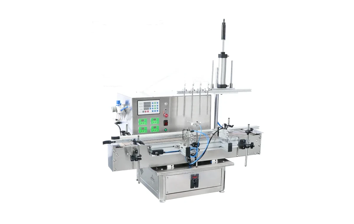
Solvent filling machines
For flammable, low-viscosity or specialist solvent products where line controls and environment need review.
Read moreATEX and hazardous-area projects
ATEX filling should be approached as a project specification, not as a simple product label. The liquid, vapour behaviour, flash point, container, site zoning, utilities and installation environment all affect the filling equipment.
Specification
A flammable liquid can change the specification of the filler, electrical components, pneumatics, controls, conveyors and installation plan. The correct answer depends on the liquid and the area in which the machine will be installed.
Choose your equipment
Choose the option that best matches the solvent, container and production environment you need to handle.
For flammable, low-viscosity or specialist solvent products where line controls and environment need review.
Read more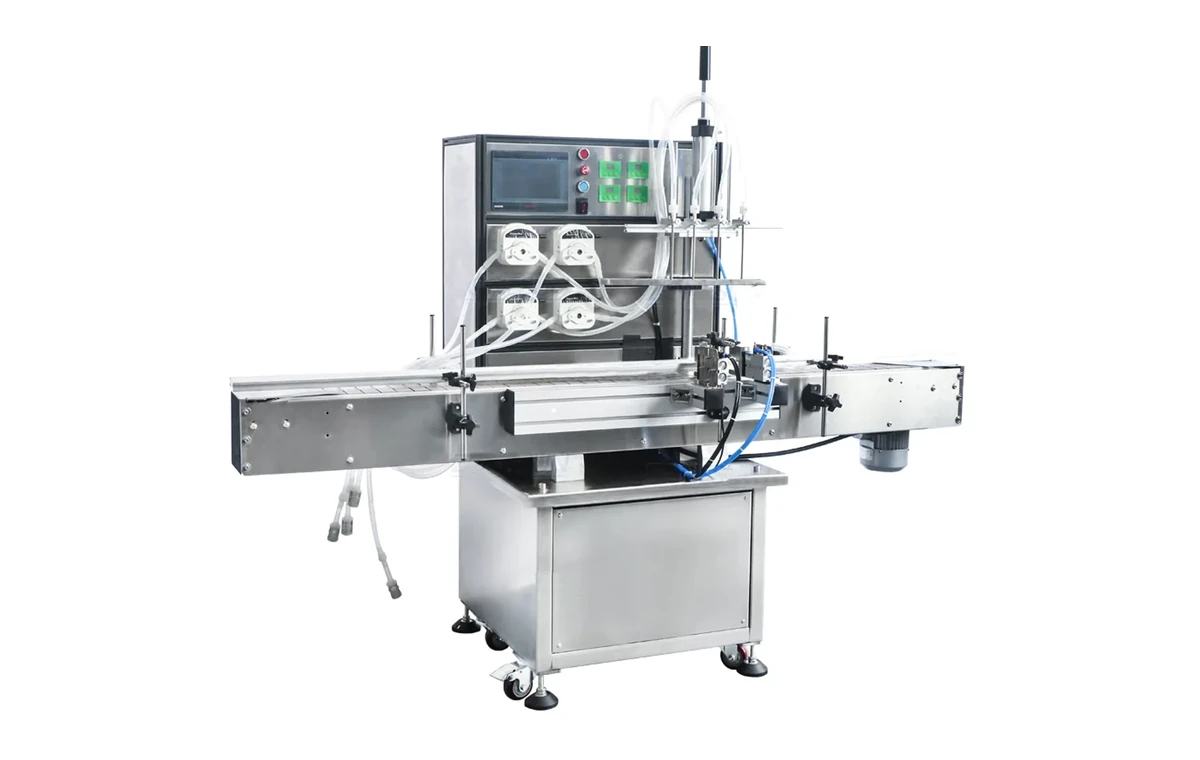
For higher-output projects where ATEX considerations need to be integrated into an automatic line plan.
Read more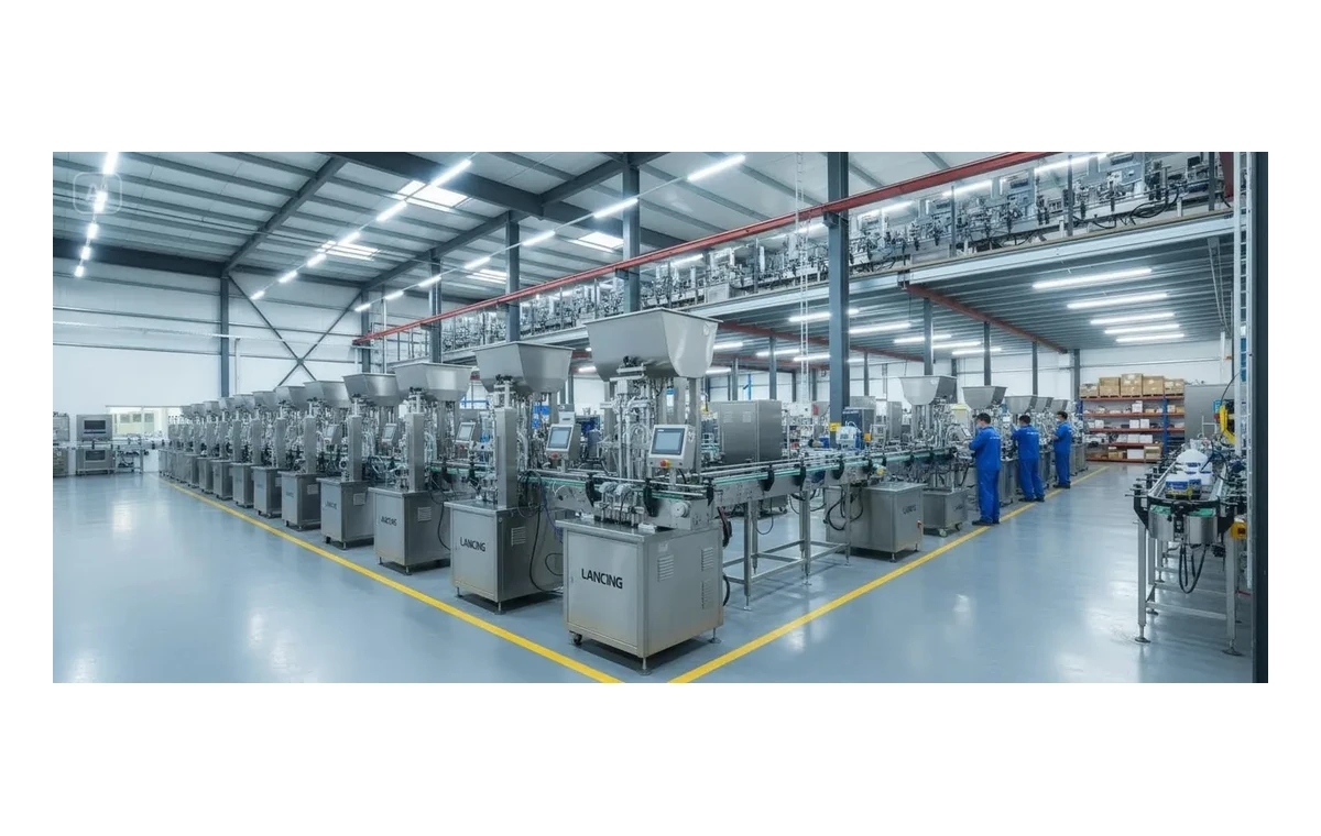
For projects where capping, conveyors, labelling and coding also need to be considered in the ATEX discussion.
Read moreComparison
| Question | Why it matters | Action |
|---|---|---|
| Is the liquid flammable? | The liquid properties influence the required machine and controls. | Provide SDS and product details early |
| Where will the machine run? | Hazardous area zoning affects specification and installation. | Describe the production area and utilities |
| How is the container closed? | Open containers, caps and vapour control affect the wider line. | Review filling and capping together |
| What output is required? | Automation level changes equipment scope and layout. | State realistic daily and peak targets |
Note
These notes are intended to help you prepare an equipment enquiry. They do not replace a formal DSEAR, ATEX, site-risk or compliance assessment. Final specification should be confirmed using product data, installation conditions and competent engineering review.
FAQ
Possibly. The answer depends on the solvent, flash point, vapour behaviour, container, filling environment and site zoning. Send the SDS and site context for review.
Yes, but the full line must be considered carefully, including container handling, capping, controls, utilities and installation area.
Do not assume that. Hazardous-area projects need proper review before equipment is selected or installed.
Speak to Lancing
Send the product, fill volume, container, closure and target output. Include SDS and compatibility notes where relevant.
Safety and compliance boundary
The employer’s DSEAR duties, hazardous-area classification, process controls, ventilation, static control, product supply, building and operating procedures must be considered alongside equipment intended for the classified area. Final zone, equipment category, gas group, temperature class, marking, conformity assessment and installation requirements must come from the competent project assessment. This page supports commercial scoping only and does not replace that work.
DSEAR and equipment selection
HSE guidance explains that employers must classify areas where explosive atmospheres may occur into zones according to likelihood and persistence. The product SDS helps identify hazards, but HSE also makes clear that an SDS is not itself a risk assessment. Provide the relevant sections of the SDS together with the site’s DSEAR information, area-classification drawing and operating conditions.
| Project input | Why it affects the machine | Evidence expected |
|---|---|---|
| Product and operating temperature | Flash point, vapour generation, conductivity, viscosity and compatibility can change with temperature and formulation | Current SDS, formulation/concentration, temperature range and process description |
| Hazardous-area classification | Zone, extent, gas group and temperature class influence equipment and installation selection | Competent classification drawing and written basis, including normal and foreseeable abnormal releases |
| Ventilation or extraction | Release rate and vapour control affect the surrounding atmosphere and operator exposure | Site design basis, airflow or extraction interface, monitoring and failure response |
| Bonding and earthing | Conductive equipment, containers and transfer systems may require a defined static-control strategy | Connection points, verification method, permissives/interlocks and site procedures |
| Containment and drainage | Spills can create fire, exposure and environmental risks and may spread beyond the fill point | Bund or tray capacity basis, compatible construction, safe drainage and recovery plan |
| Complete line boundary | Cappers, conveyors, sensors, printers and operators may sit within or affect the classified area | Layout, battery limits, equipment list, control interfaces and responsibility matrix |
Static, vapour and spill control
Review the bulk container, transfer pump, hoses, filler, receiving pack, capper and waste route. Bonding and earthing arrangements need accessible connection points and a defined method of checking continuity; where a permissive is required, agree how the machine behaves if the connection is absent. Non-conductive containers and low-conductivity liquids require specialist consideration rather than a generic earth lead.
Vapour extraction or local exhaust is site- and product-dependent. Define capture location, duct interface, compatible materials, airflow monitoring, discharge route and the machine response to extraction failure. Likewise, a drip tray is not a complete containment plan unless capacity, drainage, recovery and safe cleaning have been agreed.
For specialist machine comparisons and current ATEX project information, use the dedicated ATEX Filling Machines UK site. HSE’s ATEX and explosive atmospheres guidance and SDS guidance should also be reviewed by the competent project team.
FAT and handover
The acceptance protocol should cover the agreed products and packs, controlled start and stop, emergency stop, loss of air or power, extraction or earthing permissives where specified, no-container/no-fill logic, spill response, alarm reset and restart. Record the equipment configuration, component markings, software version, settings and unresolved actions. Site acceptance must then verify the installed utilities, bonding, extraction, layout and operating procedures; a factory test cannot prove the completed site installation.
Competent site team defines DSEAR risks, zone and operating controls.
Machine category, materials, controls and interfaces are written against that assessment.
Documents, markings, safety functions and representative filling tests are recorded at FAT.
Installation, extraction, bonding, utilities, procedures and training are confirmed before use.
ATEX project FAQ
No. The SDS provides hazard information, but the workplace classification depends on the process, release sources, ventilation, frequency and duration of an explosive atmosphere. A competent area-classification assessment is required.
No. Electrical and non-electrical ignition sources, static, mechanical heating, materials, valves, instrumentation and the complete installation still require assessment and the correct equipment specification.
Sometimes, if the site assessment and layout support that boundary. Product carryover, open containers, conveyor transfer and vapour release can affect where the classified area extends, so the complete process needs review.
Define the conductive items, receiving containers, transfer system, connection method, verification criteria and machine response to a failed connection. The design must suit the actual product and site procedure.
No. FAT can verify agreed machine functions and documentation before dispatch. The employer’s workplace assessment and the installed system, including ventilation, earthing, building and procedures, must be verified separately at site.
The applicable conformity route depends on the equipment, intended use and current product-safety law. The project should confirm the required marking and documentation with competent conformity-assessment advice rather than relying on a generic website statement.
ATEX project scoping
Send the product, containers, fill range, target output, site classification, extraction, static-control and line-layout information available.
Project evidence gates
A hazardous-area project should not rely on a single “ATEX required” note. The basis needs to remain traceable as the layout, product route, equipment list and controls develop. Each project stage should close defined evidence before the next commitment, while recognising that the employer’s workplace assessment and the machine supplier’s equipment scope are related but not interchangeable.
| Project gate | Evidence available before the gate | Decision or output to close |
|---|---|---|
| Enquiry qualification | SDS, formulation and temperature, process description, packs, output, preliminary layout and known site classification | Whether specialist hazardous-area review is required and which information is still missing |
| Order specification | Competent DSEAR/area information, equipment boundary, gas group and temperature requirements where applicable, extraction/static/containment concept and utilities | Written machine category and construction basis, exclusions, interfaces, documents and acceptance plan |
| Design review | Equipment list, component markings, layout, product path, control philosophy, safety functions and interface matrix | Approved design or recorded actions with owners and retest/approval dates |
| Factory acceptance | Agreed test product or safe representative, packs, software/configuration record, document schedule and test protocol | Witnessed filling and safety-function results, marking/document review and controlled open-action list |
| Installation and SAT | Installed utilities, extraction, bonding/earthing, containment, guarding, interfaces, procedures and training plan | Site verification of the completed installation, action close-out and authority to enter production under the employer’s controls |
Document register
The project record should identify equipment and protective systems by tag or location, with the relevant marking, certificate or declaration, instructions and installation conditions. It should also capture non-electrical ignition risks, static-control provisions, extraction or ventilation interfaces, software and settings that affect safety functions, and the procedures needed for inspection and maintenance.
Changes after the design review must be controlled. A replacement sensor, motor, valve, hose or container material can affect the original basis, so the handover documents should state how substitutions and later modifications are reviewed.
Authoritative and specialist routes
Use HSE’s DSEAR overview and ATEX and explosive-atmosphere guidance as authoritative starting points for the employer’s assessment. Continue to ATEX Filling Machines UK for the specialist equipment route, while this site retains the chemical product, filling and pack evidence.
Hazardous-area project boundary
ATEX equipment selection cannot be separated from the employer’s DSEAR assessment, area classification, product handling and working environment. The machine brief should identify the hazardous zones and gas or vapour information provided by the site, the equipment boundary, connected machinery, extraction, bonding and earthing, containment, cleaning and the interfaces that require confirmation by a competent person.
| Input | Provided or approved by | Why it changes the machinery scope |
|---|---|---|
| Product SDS and operating temperature | Product supplier and employer | Supports hazard review, vapour and compatibility decisions; an SDS is not itself the workplace risk assessment |
| DSEAR assessment and area classification | Employer with competent support | Defines where explosive atmospheres may occur and the protection level expected of equipment in each area |
| Extraction and discharge route | Site designer or employer | Affects vapour capture, interlocks, duct interfaces and safe discharge |
| Bonding and earthing philosophy | Site and machine designers | Defines connection points, monitoring, permissives and responsibility for mobile containers or transfer equipment |
| Bulk transfer and containment | Shared project scope | Changes pumps, hoses, valves, spill retention, isolation and emergency response |
| Connected capper, labeller and conveyor | Line integrator and site | All equipment and interfaces that enter or affect the classified area need coordinated review |
HSE explains that DSEAR requires employers to assess dangerous-substance risks, control them and classify areas where explosive atmospheres may occur. Use current official HSE DSEAR guidance with competent project advice.
Controlled evidence
Record them in the chemical filling URS, review changes through the management-of-change process and define required declarations, drawings, manuals and test records in the documentation register.
ATEX project input
Include the current SDS, area classification, layout, extraction, static-control philosophy and connected equipment.
Hazardous-area questions
These answers are written for early project definition. Final machine suitability depends on the actual formulation, packs, site conditions and representative testing.
Machine suitability concerns the defined equipment, intended use and evidence supplied for that scope. Site compliance concerns how the employer installs, integrates, operates, cleans and maintains the equipment within the real workplace, including other ignition sources, ventilation, transfers, people and emergency arrangements.
Neither side should be hidden behind a single phrase such as “ATEX compliant”. The machine-suitability and site-compliance guide shows how to record the boundary.
The employer or site duty holder is responsible for the workplace assessment and should provide competent hazardous-area information for the location in which the equipment will operate. The machinery supplier can use that information to define the equipment scope, interfaces and evidence, but should not infer a zone from the product name alone.
Provide release sources, ventilation, process temperatures, transfer arrangements, abnormal conditions and the classified drawings or schedule before the final equipment specification is released.
No. A marked component only addresses that component within its declared conditions. The assembled machine and installed line also include mechanical ignition sources, static, controls, wiring, sensors, motors, conveyors, extraction interfaces, flexible connections and activities such as sampling, cleaning and maintenance.
Require a schedule that identifies the assessed boundary, equipment categories or protection concepts where relevant, installation assumptions and documents supplied. Site integration must then be checked against the employer’s DSEAR assessment.
Include filling start-up and shutdown, priming, sampling, product change, hose connection, spill recovery, cleaning, draining, filter or seal replacement, fault finding and maintenance. These tasks may open the product path or defeat the normal containment that exists during steady production.
For each task, define who performs it, what can be released, where vapour or liquid goes, how ignition sources are controlled and what isolation or verification is required before work starts.
Speak to Lancing
Include the current SDS, process temperature, transfer method, area-classification information, extraction and containment interfaces, pack samples and intended operating tasks.
Evidence and responsibility boundary
The filling-machine specification should state the product hazard information and the equipment boundary, but it cannot replace the employer’s site-specific assessment. HSE guidance explains that DSEAR requires employers to assess and control fire and explosion risks from dangerous substances, while a safety data sheet supports risk assessment but is not the assessment itself.
| Evidence item | Machine-project input | Site or employer input |
|---|---|---|
| Product hazard basis | Approved product identity, SDS revision and machine design assumptions | Confirmation of substances, quantities, work activities and foreseeable releases on site |
| Area classification | Equipment category or protection requirements stated in the enquiry and design review | Competent classification of the installation area and confirmation of surrounding equipment and activities |
| Vapour and extraction interface | Fill-point connection, enclosure or extraction assumptions within the supplied scope | Ventilation system, discharge route, monitoring, maintenance and proof that the complete installation performs as intended |
| Earthing and bonding | Machine connection points and equipment design provisions | Site earth, container/bulk-transfer arrangements, inspection regime and operating procedure |
| Commissioning evidence | Supplier checks for the supplied machinery and agreed functions | Installed-system verification, workplace procedures, training, emergency arrangements and continuing inspection |
Use the current HSE DSEAR guidance and HSE safety data sheet guidance when preparing the site brief. Product compatibility, operator health exposure and explosion protection are connected but separate decisions.
Where the machine includes replaceable Ex-related or static-control components, include them in the critical spares and replacement-control register; a substitute part must not alter the approved protection concept.
Release source definition
The filling point can release vapour during container filling even when the liquid transfer itself is closed upstream. The competent site assessment should therefore consider the container opening, nozzle movement, fill profile, extraction capture, drips, overfill, hose or fitting failure and the non-routine tasks that open the product path.
| Interface | Evidence needed | Design responsibility to identify |
|---|---|---|
| Container vent path | Neck and nozzle geometry, displaced-gas route, vapour properties, fill profile and extraction assumptions | Site assessor, extraction designer and machine supplier boundary |
| Routine drips and overfill | Collection points, detection, isolation, safe removal and restart method | Machine tray versus process-area containment |
| Credible larger release | Hose, fitting, valve, supply and container failure cases | Site secondary containment and emergency plan |
| Cleaning and maintenance | Drain, flush, purge, waste and equipment-opening sequence | Employer procedures and supplied isolation facilities |
The displaced-air guide explains the pack geometry, while the secondary-containment guide separates local collection from the wider site system. Neither replaces a competent application-specific assessment.