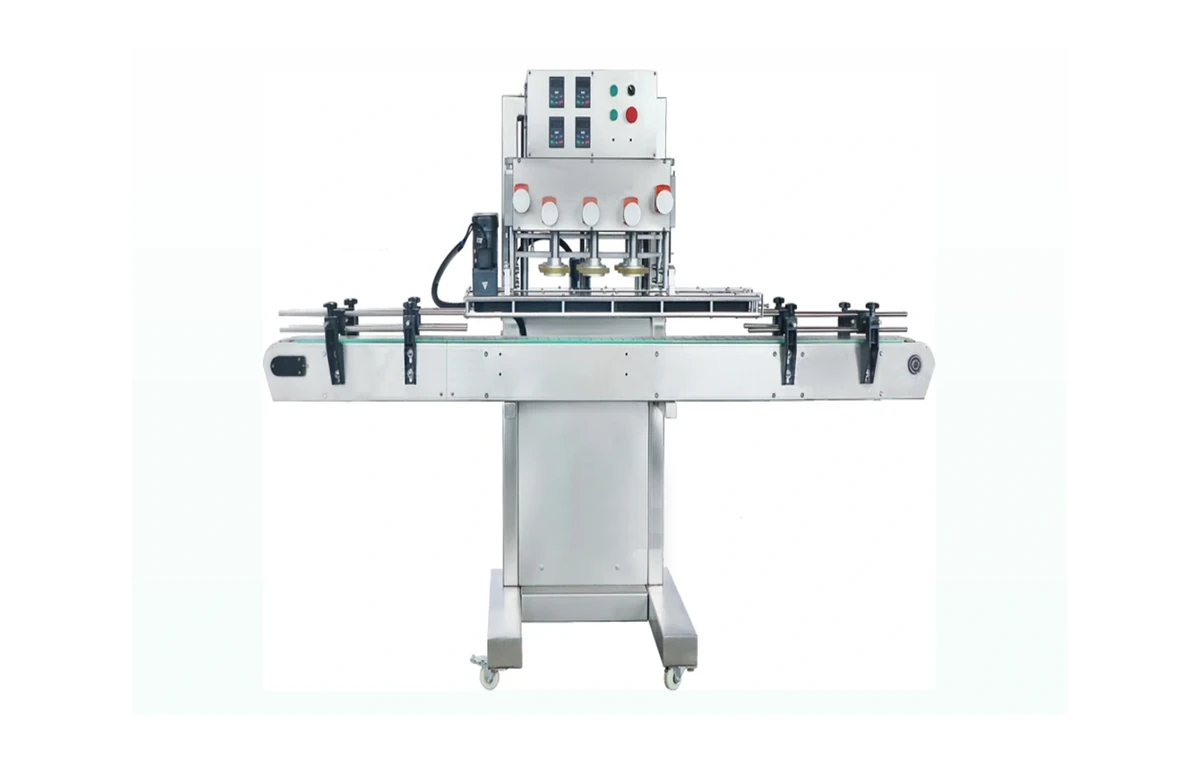
Screw capping machines
Torque-controlled options for standard bottles, HDPE containers and selected chemical packs.
Read moreCapping and closures
The closure handling can make or break a chemical filling line. Screw caps, triggers, pumps, bungs, lugs, plugs and ROPP closures all have different handling, torque, feed and changeover requirements.
Specification
Chemical containers need dependable closure control because leaks, liner compression, thread engagement and pack stability all affect finished-pack quality. A capper should be selected around the actual bottle, neck finish, cap, product and line speed.
Choose your equipment
Use closure type first, then automation level and line integration.
Torque-controlled options for standard bottles, HDPE containers and selected chemical packs.
Read more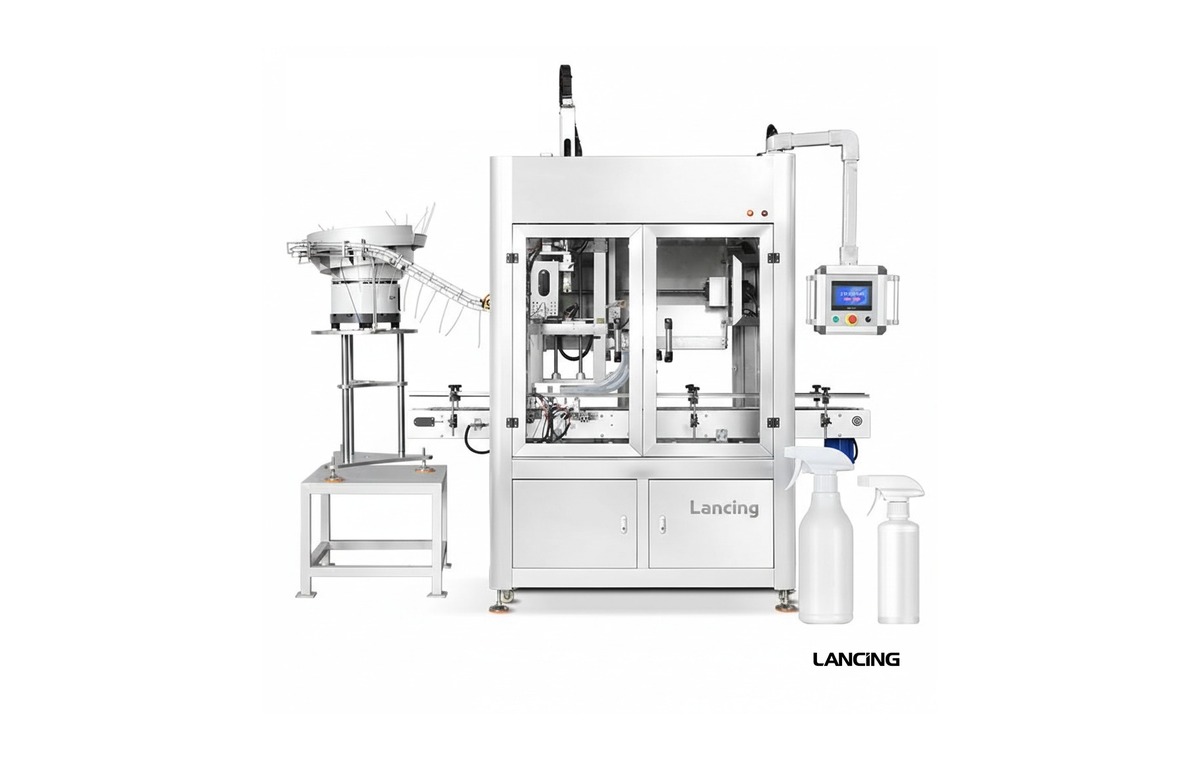
Specialist handling for cleaning products, sanitisers, sprays and dispenser closures.
Read more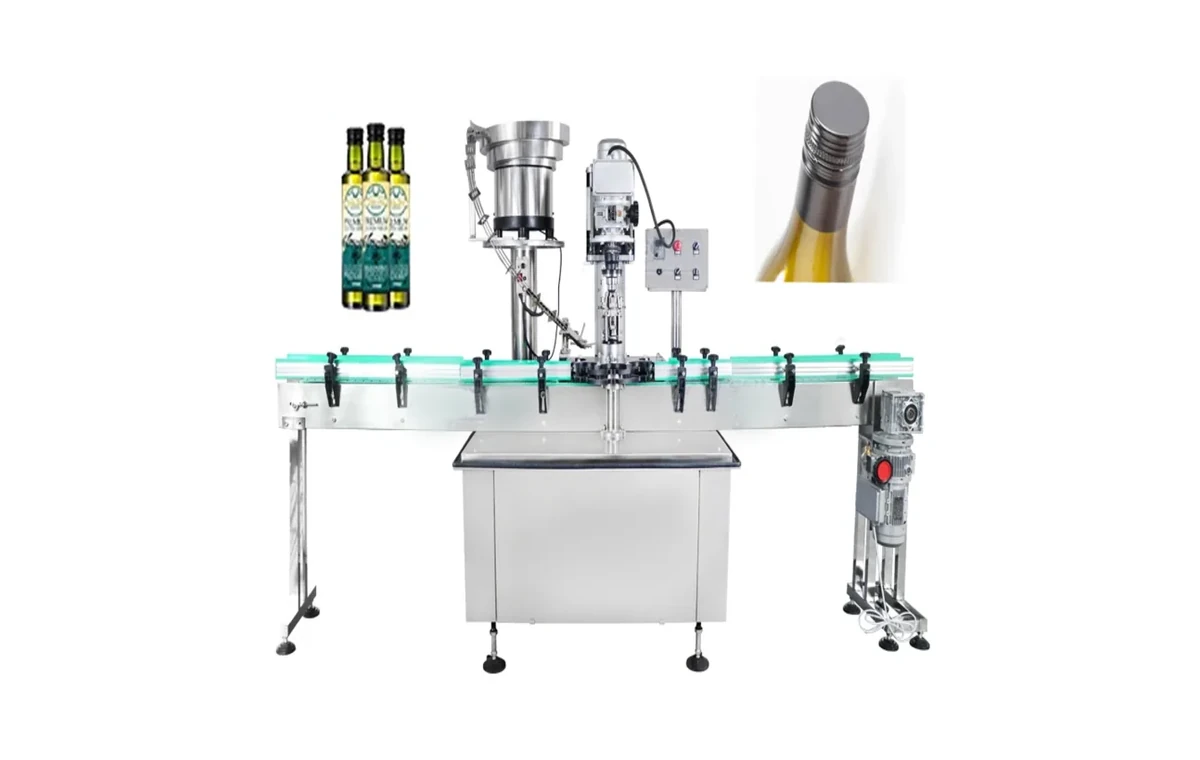
Options for aluminium closures and specialist pack formats where standard screw capping is unsuitable.
Read more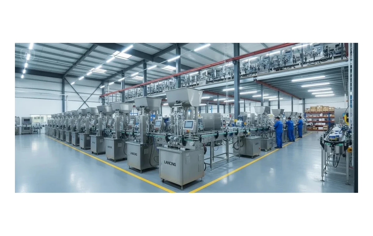
Balanced lines where filling output, capping speed and labelling requirements are specified together.
Read moreComparison
| Detail | Why it matters | Example |
|---|---|---|
| Cap diameter and height | Determines chuck, spindle or handling equipment | 28mm screw cap, pump, trigger |
| Bottle neck finish | Affects thread engagement and torque repeatability | Thread style, neck size, liner |
| Torque target | Defines tightening method and quality check | Opening-force or torque range |
| Cap presentation | Manual placement or automatic feed changes the equipment | Bowl feeder, cap elevator, hand placed |
| Filled-pack stability | Chemical packs can be light, tall or flexible | Bottle guides, conveyor control |
Process
Screw, trigger, pump, ROPP, press cap or specialist lid.
Tall, flexible, tapered or lightweight containers can affect capper choice.
Manual placement, bowl feeding and cap elevators have different cost and layout implications.
Filling output, capping speed and labelling must match practical production targets.
FAQ
Start with closure type and bottle stability. Screw caps, pumps, triggers and ROPP closures usually need different capping and feeding methods.
Sometimes, but it depends on cap diameter, cap height, thread style, torque range, bottle stability and how often formats change.
Yes. A fill-cap-label line is often the better choice when capping speed and closure control must match the filler.
Speak to Lancing
Send the product, fill volume, container, closure and target output. Include SDS and compatibility notes where relevant.
Closure engineering
A closure that runs well on an empty sample can behave differently after filling. Product around the neck, bottle squeeze, foaming, handle position and conveyor pressure can affect cap pickup, thread engagement, trigger alignment and applied torque. Use samples from normal production tolerances and include the filler-to-capper transfer in the trial.
| Closure route | Main variables | Evidence to request |
|---|---|---|
| Screw cap | Thread start, cap diameter/height, neck finish, bottle support, chuck or spindle contact and target torque | Applied/removal torque method, cross-thread rate, seal result and cap damage inspection |
| Trigger sprayer | Dip-tube length, trigger orientation, cap thread, bottle stability and component presentation | Tube insertion, orientation window, torque, leak check and sustained feed test |
| Pump dispenser | Long dip tube, pump height, locking position, head orientation and bottle support | Insertion success, pump damage, torque/seal result and line transfer |
| ROPP or crimp closure | Cap material, neck finish, tooling profile, bottle height and support | Formed thread/crimp, tamper evidence, finish inspection and destructive checks where agreed |
| Large jerrycan cap | Handle interference, neck location, high torque and container distortion | Tool engagement, reaction support, torque method, leak/seal check and operator ergonomics |
Component feeding
Automatic capping depends on the cap elevator, bowl, sorter, chute or pick-and-place system delivering components in the correct orientation without scuffing or jamming. Provide a statistically useful batch from normal suppliers and include mould variation, liners, tamper bands, dip tubes and packed/storage condition. Agree how low cap level, blocked chute and malformed components are detected and recovered.
Residue can change friction, torque and seal performance. The filler trial should include external neck and thread cleanliness, nozzle withdrawal and the time between filling and capping. Where corrosive or solvent product may remain on the closure area, include compatible collection, guarding and operator protection.
Specialist capping site
This chemical page explains how product and filled-pack condition affect capping. Detailed screw, trigger, pump, ROPP and closure-feeding comparisons are owned by Capping Machines UK. Keep both specifications aligned so the filler delivers a pack the capper can close consistently.
Chemical capping FAQ
Use the closure and container supplier’s approved window and define the test instrument, timing and conditioning. Do not invent one universal torque from cap diameter alone.
Yes in suitable projects, but dip-tube control, trigger orientation, bottle support, cap feeding and component quality require representative trials.
Possible causes include neck contamination, misalignment, unstable bottles, cap presentation, excessive downward force, poor component tolerances or unsuitable speed. Test filled packs from normal production supply.
Where seal integrity is critical, agree a product-appropriate test and acceptance method. The capper’s torque result alone may not prove the complete closure seal.
Possibly with change parts or tooling, but very different closures may need separate feeding and application modules. Document changeover time, tools, settings and verification.
Closure trial
Include drawings, target torque or seal requirements, closure batches, output and required inspection method.
Closure integrity
A capper can apply a repeatable setting while the finished pack still leaks or becomes difficult to open. Neck finish variation, thread condition, liner compression, product on the land area, container panel strength, induction sealing and time after application all affect the result. Use filled production components when defining torque and seal acceptance.
| Pack feature | Machine or process influence | Evidence to retain |
|---|---|---|
| Container neck and thread | Guide alignment, chuck or spindle engagement and side pressure | Approved container drawing or samples, dimensional tolerance and damage inspection |
| Closure and liner | Presentation, orientation, downward load, tightening method and applied setting | Closure-supplier guidance, lot identity and application/removal test results |
| Filled neck condition | Nozzle cut-off, splash, foam and bottle movement before capping | Visual or defined cleanliness check on representative filled packs |
| Container strength | Gripping, belt pressure, chuck load and filled-product temperature | Evidence that the pack is not distorted, scuffed or destabilised |
| Seal process | Induction-seal presence, cap seating and any retorque requirement | Seal inspection and integrity method agreed with pack and liner suppliers |
| Storage and transport | Torque relaxation, thermal change, inversion, vibration and handling | Site-approved leak and opening checks after representative dwell and handling |
Finished-pack test plan
Define whether the site checks application torque, removal torque, closure height, tamper evidence, liner presence, seal integrity, leak resistance or a combination. Record test equipment, timing after capping, sample conditioning and failure action. The chemical pack integrity guide provides a structured plan.
Chemical capping trial
Include container and closure lot samples, liner or seal details, torque method and realistic handling checks.
Closure-quality questions
These answers are written for early project definition. Final machine suitability depends on the actual formulation, packs, site conditions and representative testing.
Measured removal torque can change as the closure, liner, thread and bottle relax, warm, cool or interact with product residue. Application torque and later removal torque are not the same measurement, so the test method, delay, product condition and pack orientation must be defined.
Use closures and bottles from normal supply tolerances. The cap-torque change guide sets out the pack and process variables to challenge.
A flexible bottle can ovalise, shorten or twist under top load and gripping pressure. That can move the neck away from the chuck, change thread engagement, disturb liquid near the opening or produce a torque reading that looks acceptable while the liner is not seated consistently.
Specify bottle support, guide pressure, chuck force and filled-pack condition together. Test the lightest, softest and most dimensionally extreme samples, not only a rigid nominal bottle.
Use more than a visual check. Define neck engagement, orientation where required, dip-tube condition, closure height or position, torque or axial force where meaningful, leakage or seal evidence and function of the trigger or pump after storage or handling.
Challenge bent dip tubes, supply variation, partly presented closures and a wet neck. The acceptance method should identify a closure that is present but not functionally sealed.
Run containers that represent the normal clean condition and the credible worst condition produced by filling, including foam, drips or a small amount of product on the sealing surface. Observe closure pick-up, cross-threading, torque, liner or induction-seal performance, leakage and contamination of capping parts.
The objective is not to accept a dirty process by design; it is to understand the boundary and set the fill, wipe or reject controls needed to keep the closure operation reliable.
Speak to Lancing
Include bottles across tolerance, caps or pumps, liners, dip tubes, product samples, the intended torque or seal method and downstream handling.
Closure quality after maintenance
Chucks, belts, rollers, grippers, cap chutes, escapements, sensors and format parts can change closure handling as they wear or are replaced. A part that appears dimensionally similar may alter cap engagement, bottle squeeze, applied torque, liner compression or trigger orientation.
| Part or setting | Possible finished-pack effect | Verification after intervention |
|---|---|---|
| Chuck, head or torque clutch | Under-tightening, over-tightening, cap damage or inconsistent application | Test the approved closure range on filled production-tolerance bottles and use the agreed torque or integrity method. |
| Side belts, grippers and guides | Bottle squeeze, rotation, poor neck alignment or unstable transfer | Observe container control at minimum and maximum agreed pack tolerances. |
| Cap chute, bowl tooling and escapement | Upside-down caps, doubles, scuffing, jams or intermittent starvation | Run representative bulk closures, including tolerated supplier variation and normal replenishment. |
| Presence and reject sensors | Uncapped or mis-capped containers passing downstream | Challenge each failure state and confirm the correct pack is identified and rejected. |
Record exact approved part references and any closure-specific tooling in the chemical filling line critical spares register. Continue to use the existing pack and closure integrity guide for the final acceptance method.