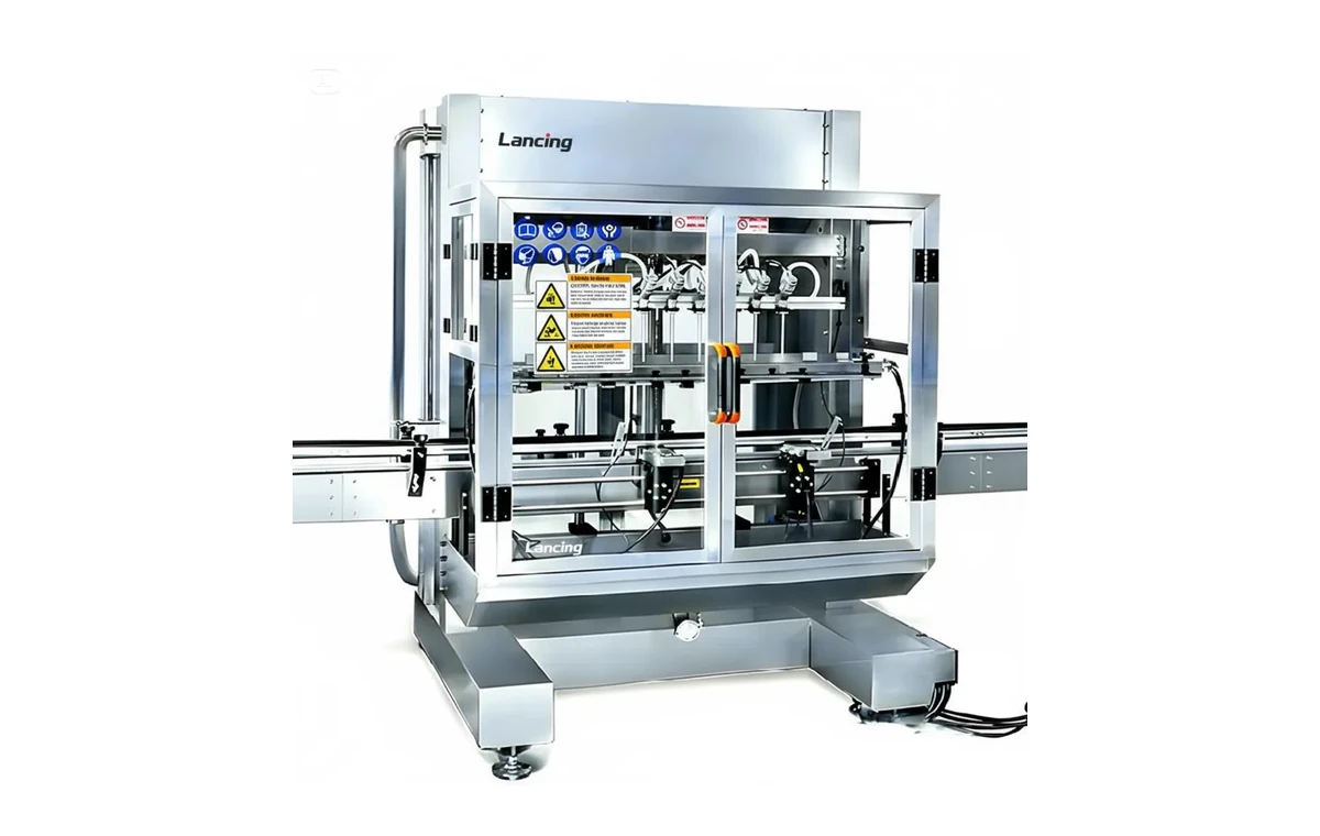
ATEX filling machines
Where the solvent or production area may require hazardous-area specification.
Read moreSolvent filling
Solvent filling projects need careful review of the liquid, container, vapour behaviour, splash control and installation area. Many solvent enquiries also overlap with ATEX and hazardous-area requirements.
Specification
A solvent may fill quickly, but the project can be shaped by vapour, ignition risk, container opening, cap handling, operator exposure, site conditions and safe handling. These points should be addressed before choosing a standard low-viscosity filler.
Choose your equipment
Use these options to prepare a complete solvent filling and closing brief.
Where the solvent or production area may require hazardous-area specification.
Read more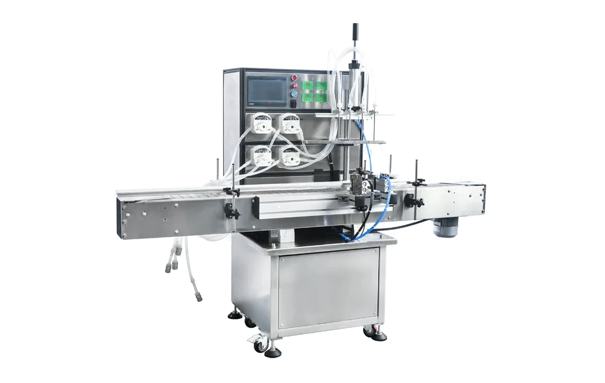
For repeated production where filling, capping and conveying need to be integrated.
Read more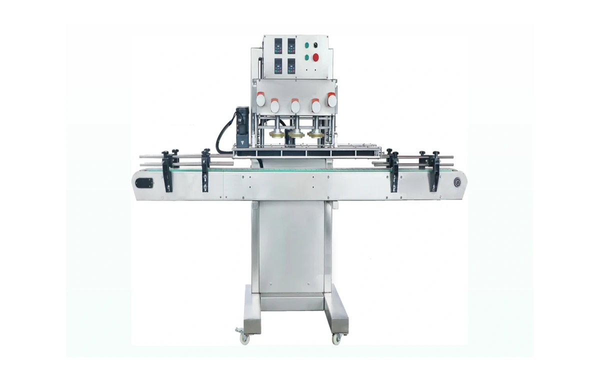
For cap torque, cap feeding, tin closure or line sealing discussions around solvent packs.
Read moreComparison
| Area | Why it matters | Briefing point |
|---|---|---|
| Ignition and vapour | Can affect the equipment and installation approach | Provide product data and site context |
| Splash and shut-off | Thin liquids may drip, splash or create presentation issues | Discuss nozzle and fill profile |
| Container compatibility | Solvents can affect plastics, seals and labels | Share container and cap samples |
| Capping sequence | Open containers may increase vapour and spill concerns | Review capping with filling |
| Ventilation and site layout | Machinery cannot be specified in isolation | Describe production area and utilities |
Note
Solvent projects should be reviewed using product data and installation conditions. Do not use a standard filler in a potentially hazardous environment without proper assessment.
FAQ
Not always, but many solvent projects require ATEX or hazardous-area discussion. The decision depends on the liquid and installation environment.
Yes, but small-bottle solvent filling needs attention to fill accuracy, splash control, closure style and vapour management.
Send SDS, fill volume, container and closure details, target output, installation environment and any existing risk-assessment notes.
Speak to Lancing
Send the product, fill volume, container, closure and target output. Include SDS and compatibility notes where relevant.
Volatility and process control
Low viscosity does not make a solvent easy to fill. Fast flow can increase splash, turbulence and vapour release, while long pauses can allow drainage or evaporation at the nozzle. The product may also affect hose, seal and pump materials. The filler, bulk supply, receiving container and surrounding area must therefore be reviewed as one process.
Review whether the nozzle should fill above the neck, enter the container or move with the rising liquid. A controlled start can reduce initial splash; a final slow stage or positive shut-off can improve cut-off. If extraction is required, define the capture point and ensure it does not destabilise containers, pull product mist into unsuitable ductwork or interfere with weighing or flow measurement.
Peristaltic systems can keep product inside tubing, but the tube must tolerate the chemistry and cyclic compression. Diaphragm, piston, gear, flow-meter and weigh routes each have different seal, leakage, pressure, aeration and cleaning implications. Confirm all internal materials, not only the pump body, and include the cleaning or flush solvent in the approval.
Cleaning and product change
A flush sequence should state the source and destination of each liquid, the quantity or endpoint, safe collection, ventilation and how the product path is left between batches. Avoid directing an unmeasured solvent flush into open waste containers. Where product recovery is planned, identify the point at which mixed or off-specification liquid is diverted and how operators recognise the change.
| Operating condition | Potential issue | Trial or control to agree |
|---|---|---|
| High initial flow into an empty bottle | Splash, turbulence, mist or static generation | Controlled first stage, nozzle position and representative container trial |
| Production pause | Nozzle drainage, evaporation, loss of prime or first-pack error | Defined pause time, restart sequence and first-pack verification |
| Small neck or unstable pack | Misalignment, contact, spill or conveyor movement | Container guides, neck location, nozzle clearance and stop/recovery test |
| Product change or flush | Mixed product, uncontained vapour and incompatible waste | Written valve sequence, collection route, endpoint and operator sign-off |
Specialist ownership
Chemical Fillers UK covers the product and pack decisions that affect solvent dosing. Where the site has or may create a classified area, use ATEX Filling Machines UK for specialist equipment and project guidance, alongside competent DSEAR and area-classification advice. A corrosion-resistant or pneumatic filler is not automatically suitable for a flammable-liquid installation.
Solvent filling FAQ
The requirement depends on the product, release scenario, ventilation and competent hazardous-area assessment. Do not decide from the word “solvent” alone or assume ordinary equipment is suitable without assessment.
Some applications may suit peristaltic dosing, but tubing material, fatigue, permeation, flow and static considerations must be approved for the exact solvent and duty.
Potential measures include lower-turbulence filling, controlled nozzle position, suitable extraction, closed transfer and reduced open-container time. The site assessment determines the required controls.
Common causes can include drainage, loss of prime, air ingress, evaporation, changing supply head, meter limitations or container/scale effects. Reproduce starts, stops and temperature conditions during the trial.
The static-control strategy depends on the liquid, container, transfer equipment and site assessment. Conductive and non-conductive packs require different competent consideration.
Only with a documented, compatible and contained procedure. Confirm the flush liquid, sequence, endpoint, waste/recovery destination, ventilation and restart checks.
Solvent filling brief
Send the SDS, temperature, fill range, containers, classification information, extraction, static-control and cleaning details.
Site interface schedule
The machine supplier can define equipment within an agreed boundary, but the employer remains responsible for the workplace assessment and the way the completed process is installed and operated. A project schedule should show who owns each decision, what information is required and where it will be verified. This prevents an assumed site control from being discovered only at installation.
| Interface | Site information required | Machine or line response to define | Closure evidence |
|---|---|---|---|
| Bulk transfer | Source vessel, pressure or pump, hose route, isolation, temperature and return or recirculation | Connection, permissible supply window, level/pressure logic, loss-of-feed response and compatible product path | Process sketch, connection schedule and witnessed start/stop test |
| Vapour and extraction | Release assessment, capture concept, duct location, discharge route and monitoring | Hood or connection boundary, interference with weighing/containers, permissive and safe response to extraction failure where specified | Competent design basis, commissioning evidence and site verification |
| Bonding and earthing | Conductive items, container type, transfer equipment, connection method and site procedure | Accessible points, continuity or permissive interface and machine behaviour when the required connection is absent | Design record, verification method and installed test |
| Spill containment | Credible release, compatible bund/tray, drainage, recovery, segregation and disposal route | Drip capture, leak visibility, safe isolation, access for recovery and protection of controls or scales | Capacity basis, layout, material approval and spill-response test or drill as applicable |
| Operator task | Bulk connection, container presentation, cap handling, sampling, cleaning, reject removal and maintenance | Access, guarding, interlocks, safe parking, isolation and instructions for foreseeable interventions | Task review, training record and witnessed operating procedure |
| Flush and waste | Flush liquid, volume or endpoint, receiving vessel, ventilation and mixed-product classification | Valve sequence, drain points, retained volume, safe collection and restart checks | Approved procedure and representative cleaning/restart test |
Operator and maintenance boundary
Connecting a hose, changing a nozzle, clearing a misaligned container, taking a sample or draining a machine can release more vapour or liquid than a stable automatic cycle. Include those foreseeable tasks in the DSEAR and COSHH review, then specify isolation, ventilation, spill control, tools, personal protection and restart checks accordingly. The SDS is an input to that work; it is not the workplace risk assessment.
HSE’s DSEAR guidance explains the employer’s duty to assess and control risks from dangerous substances, while its ATEX and explosive-atmosphere guidance covers classification and equipment considerations. Use competent project advice to apply that guidance to the actual formulation, release scenario and site.
Specialist hazardous-area ownership
This page owns the solvent product-path and pack discussion. Continue to ATEX Filling Machines UK where the project requires specialist hazardous-area equipment selection, and use the local ATEX project brief to organise the information supplied with the chemical filling enquiry.
Machine and site interfaces
The filler cannot be assessed in isolation from the bulk source, transfer hose, container, operator, extraction and downstream line. The project interface register should identify who designs, supplies, installs, verifies and maintains each control. Assumptions about the product temperature, ventilation or classified area should remain open until approved by the responsible site specialists.
| Interface | Questions for the project | Evidence before release |
|---|---|---|
| Bulk source and transfer | Is product pumped, pressure-fed or drawn by suction; how is isolation, low level and hose disconnection controlled? | Flow diagram, battery limits, hose and valve schedule, shutdown and spill response |
| Vapour capture | Where is vapour generated and how are hood position, airflow, interlocks and discharge arranged? | Site extraction design and commissioning results linked to machine permissives where required |
| Static control | Which fixed and mobile conductive parts require bonding or earthing, and is continuity monitored? | Approved philosophy, connection points, test method and operator sequence |
| Container filling | Does top, diving or bottom-up filling best control splash, foam, vapour release and residue on the neck? | Representative trial at normal and boundary product conditions |
| Spill containment | Where can product collect, how is it detected or removed, and what materials contact the spill? | Containment volume and route, compatible construction, cleaning and emergency procedure |
| Cleaning and changeover | How are retained solvent, rinse fluid, vapour and waste isolated and disposed of? | Approved sequence, waste route, ventilation requirement and first-off release check |
Use official HSE DSEAR guidance and the employer’s competent assessment. The machine supplier can support equipment information, but the employer retains responsibility for workplace risk control.
Keep assumptions controlled
The chemical filling URS guide provides a structure for responsibilities and acceptance. Use management of change when a solvent, temperature, area classification, extraction system, container or cleaning route is altered.
Solvent filling brief
Include the SDS, operating temperature, DSEAR information, area classification, bulk transfer, extraction, static control and containment.
Solvent-project questions
These answers are written for early project definition. Final machine suitability depends on the actual formulation, packs, site conditions and representative testing.
Define what leaves the container as liquid enters, whether vapour is captured locally or returned through a controlled route, and how the arrangement behaves during priming, a stopped nozzle, container change and spill recovery. A generic room-extraction statement does not define capture at the release point.
The site assessment should determine the required control. The filling specification should then state the connection, permitted pressure or vacuum, monitoring, interlocks and responsibility for commissioning that interface.
Yes. Changing head pressure, pump inlet conditions or upstream valve position can alter flow, prime stability and cut-off even for a thin liquid. Low boiling or volatile products can also be sensitive to pressure drop, air ingress and temperature. The machine should be assessed across the real minimum and maximum supply conditions.
Provide the source-vessel arrangement, transfer pump data, line size, height difference, operating temperature and what happens as the source empties.
Maintenance, sampling and cleaning can create releases that do not occur during closed automatic filling. Opening a filter, disconnecting a hose, draining a pump or placing a sample container may expose people and introduce ignition sources outside the normal machine cycle.
Design the isolation, drain, purge or flush route and access before order. The safe system of work, competent assessment, personal protective equipment and emergency arrangements remain site responsibilities.
Consider a dedicated path where different solvents attack different seals or hoses, residues cannot be verified, mixtures could create a new hazard, changeover requires extensive open handling, or a return line makes line clearance uncertain. Campaign production may reduce changes but does not remove the need for documented clearance.
Compare shared and dedicated arrangements using compatibility, retained volume, clean endpoint, connection error risk and the frequency of product change.
Speak to Lancing
Send the SDS, fill temperature, transfer conditions, container and closure samples, area-classification information and the expected extraction and containment connections.
Non-routine solvent tasks
A solvent filling line may be controlled during normal automatic production but open the product path during priming, filter changes, hose disconnection, nozzle cleaning or fault recovery. Those tasks can create different vapour, splash, static and operator-exposure conditions from the standard filling cycle and should be designed and assessed explicitly.
HSE guidance treats an SDS as an input to the employer’s risk assessment rather than a complete assessment. The project should therefore record which controls are part of the supplied machine and which depend on the installed workplace, procedures and maintenance system.
Include solvent-compatible replacement items in the critical spares register, and re-verify leak tightness, cut-off and quantity performance after any intervention that opens the product path.
Vapour and release path
As solvent enters a container, the existing air and any vapour must leave. The route depends on the neck, nozzle, filling head and extraction arrangement. A free annular gap may be sufficient for a non-volatile product trial, but it must not be assumed to provide safe vapour control for a flammable or harmful solvent application.
Record where displaced gas is expected to travel during normal filling, priming, restart and the final high-level phase. Then define the separate response to nozzle drips, container overfill, a damaged pack, hose disconnection or pump/valve leakage. Extraction, hazardous-area measures and secondary containment are related controls, but one does not replace the others.
Continue with the container venting and displaced-air guide and the secondary-containment and bunding guide.