Liquid pulses or rises around the nozzle
Check gas clearance, flow acceleration, nozzle depth, supply pressure and whether the liquid seals the neck opening.
Pack and nozzle interface
Relate the container neck, nozzle clearance, fill profile and product behaviour so incoming liquid does not trap or compress the gas already inside the pack.
Direct answer
The gas normally leaves through the clearance between the nozzle and the neck, through a separate vent path, or through a purpose-designed filling head. If the available path is too small for the fill rate and product behaviour, back-pressure and turbulence can cause bubbles, foam, splash, surging, false level response or deformation of flexible containers.
Specify the smallest neck, proposed nozzle outside diameter, insertion depth, fill profile, container stiffness, product temperature and vapour characteristics. Prove the route with representative packs and product conditions; a dimensional drawing alone cannot show every dynamic effect.
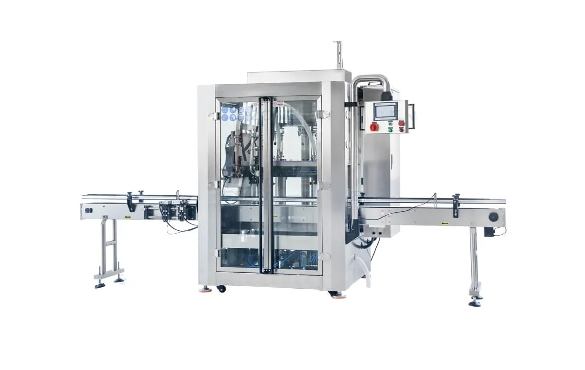
The clearance available at the start, middle and end of the fill can be different, especially with a diving nozzle or a tapered container neck.
Variables
| Variable | What can change | Trial evidence |
|---|---|---|
| Neck and bung opening | Available annular clearance, offset openings, threads, neck finish and restrictions below the visible mouth | Actual samples or controlled drawings for the smallest and most restrictive pack |
| Nozzle geometry | Outside diameter, outlet shape, insertion depth, movement, shut-off parts and any separate vent tube | Nozzle drawing and observed clearance through the complete stroke |
| Fill profile | Initial, bulk and final flow rate; acceleration; deceleration; nozzle lift and dwell | Recorded recipe, fill time, pressure/flow state and repeatable high-level behaviour |
| Product behaviour | Foam, surface tension, viscosity, entrained air, vapour, temperature and wetting of the neck | Representative product at the approved operating extremes |
| Container response | Panel flex, base stability, neck movement and interaction with guides or clamps | Empty, partly filled and full pack observations |
| Headspace and closure timing | Last-stage restriction, foam collapse, vapour release and time before capping | Agreed fill level, settled condition, neck cleanliness and closure sequence |
Symptoms and likely interfaces
Check gas clearance, flow acceleration, nozzle depth, supply pressure and whether the liquid seals the neck opening.
Check restricted venting, air already entrained by the pump, drain-back and whether the nozzle outlet is submerged at the wrong stage.
Separate bulk-product aeration from turbulence at the nozzle and air forced through a narrow neck clearance.
Check pressure change, nozzle contact, guide-rail force, flexible panels and conveyor or clamp support.
Review jet direction, gas path, nozzle height, fill profile and the least stable container condition.
Check final-flow deceleration, retained product, foam collapse, pressure release and measurement timing.
Representative trial
Each route has output, cleaning, compatibility and vapour-management implications and must be approved for the real application.
Volatile and flammable products
For solvent or flammable-liquid projects, identify the displaced-gas source in the DSEAR assessment and define the extraction and equipment boundary with competent specialists. Review current HSE DSEAR guidance. The machine selection must follow the actual product, site classification and operating tasks.
Buyer questions
Liquid entering the pack occupies volume that was previously filled by air or vapour. That gas needs a controlled escape path. If the path is too restricted, pressure and turbulence can disturb the product jet, deform the container or cause bubbles, splash and unstable cut-off.
No. A smaller nozzle can increase clearance around it, but it can also increase liquid velocity or extend cycle time. The nozzle, flow profile, insertion depth, neck geometry and product behaviour should be tested together.
No. A diving nozzle can reduce impact and foam for some products, but the displaced gas still needs a route out of the container. The available clearance changes as the nozzle moves and the liquid level rises.
Restricted gas flow, nozzle contact, conveyor guides, vacuum effects or rapid pressure changes can deform a flexible container. Test the actual bottle at empty, partly filled and nearly full conditions.
No. Container venting describes how displaced gas leaves the pack. Vapour extraction is a site and equipment control for capturing or managing hazardous or harmful vapour. A free vent path must not be treated as an acceptable extraction design.
Speak to Lancing
Include container drawings or samples, nozzle constraints, fill range, product behaviour, target output and any vapour or hazardous-area information.